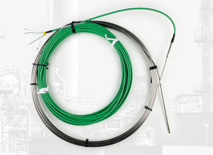
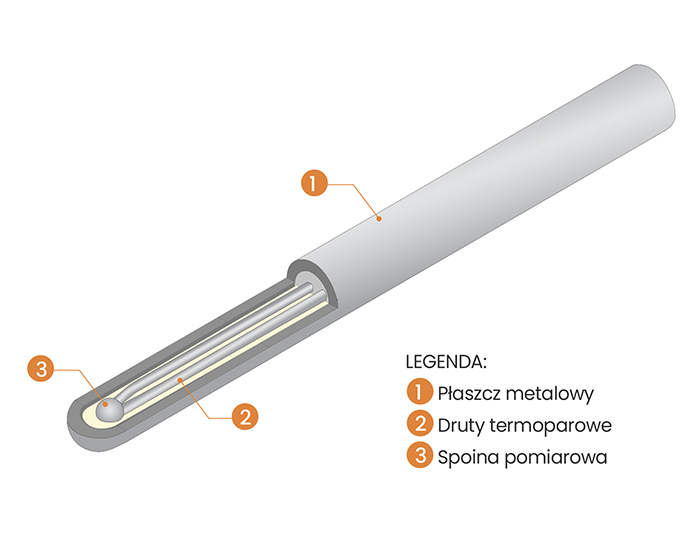
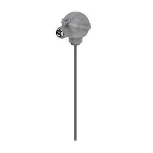
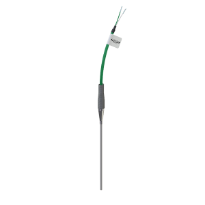
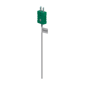
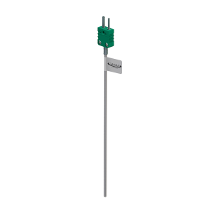
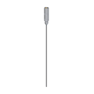
SHEATH THERMOCOUPLES
Diameter sensor
[ mm ] |
Weld type |
in water 0.4 m/s |
in the air 2 m/s |
| t50 |
t90 |
t50 |
t90 |
| Ø 0.5 |
isolated |
0.06 |
0.15 |
1.80 |
6.00 |
| grounded |
0.03 |
0.10 |
1.80 |
6.00 |
| Ø 1.0 |
isolated |
0.15 |
0.50 |
3.00 |
10.00 |
| grounded |
0.06 |
0.20 |
3.00 |
10.00 |
| Ø 1.5 |
isolated |
0.21 |
0.60 |
8.00 |
25.00 |
| grounded |
0.13 |
0.40 |
8.00 |
25.00 |
| Ø 3.0 |
isolated |
2.50 |
2.90 |
26.00 |
88.00 |
| grounded |
0.45 |
0.75 |
23.00 |
88.00 |
| Ø 4.5 |
isolated |
4.00 |
6.00 |
37.00 |
120.00 |
| grounded |
0.55 |
1.60 |
33.00 |
110.00 |
| Ø 6.0 |
isolated |
7.00 |
9.50 |
60.00 |
200.00 |
| grounded |
0.75 |
2.60 |
55.00 |
185.00 |
| Ø 8.0 |
isolated |
7.00 |
14.00 |
100.00 |
290.00 |
| grounded |
0.75 |
3.90 |
87.00 |
250.00 |
Possible measurement errors with sheathed thermocouples
Inhomogeneity errors
The heterogeneity of thermocouples can be caused by chemical composition or a change in crystal structure. Inside the thermoelectrode wires, an undesirable thermoelectric force appears, which always has a negative effect on measurement accuracy if the thermocouple is placed in an area with a temperature gradient.
The error then depends on the inhomogeneity as well as on the temperature gradient. Changes in the structure of thermoelectrode wires may occur during their coiling, folding or stretching. They are reversible. The return to the original structure occurs as a result of heating the thermocouple to the temperature of 800°C
Errors due to wrong measurement location.
Basically, the hot junction, which is a thermocouple sensor, should be placed in the hot part of the object whose temperature is being measured. If this is not met, the temperature is not measured correctly. In addition, disturbances in the temperature field can have a negative effect on the measurement. The thermal conductivity of construction materials such as insulator, thermoelectrode wires and sheath causes heat exchange to take place through them.BAsically
If the jacket is at a higher temperature than the measuring junction, heat flows towards the junction. In the same way, heat can flow away from the weld. Both cases interfere with the temperature measurement. Improvement can be achieved by appropriate design and mounting of the thermocouple. It is necessary to ensure as good as possible heat exchange between the measured object and the measuring junction.
Errors due to drift
Defects of thermocouples are not only due to mechanical damage or breakage, but also due to the force thermocouple is no longer within tolerance. This phenomenon, known as drift, happens without any external changes in temperature and can gradually change the thermoelectric force. One of the causes of drift is contamination of thermoelectrode wires due to temperature.
Example: in type K thermocouples, the drift is caused by the fact that at high temperatures, the chromium in the (+) wire oxidizes easier than nickel. Chromium is reduced and the thermoelectric force decreases. This error occurs frequently, including when the thermocouple is used in an oxygen-free atmosphere. Lack of oxygen prevents oxidation and natural formation covers. The appearing tarnish destroys the thermoelectrode wires. Temperature measurements with a type K thermocouple in an atmosphere rich in sulfur cause its interaction with the wire nickel and its brittleness. Another cause of drift is too rapid cooling of the thermocouple from the temperature exceeding 700°C.
The aging of thermocouples is the result of other processes that have nothing to do with described above. At this point, these phenomena are not described in detail, but only mentioned. As a general rule it should be assumed that thermocouples used in high temperature areas should be temporarily tested under to keep the thermoelectric force within tolerance
Errors due to wrong compensating cable
The compensating cable is needed to extend the thermocouple to the device/stand/measuring. Its connection may cause errors in measurements. To avoid this, remember that s. e. m. errors are often caused by changing the polarity of the cables when connecting, using the wrong compensating cable, too high ambient temperature or improper earthing of the shielding of the wires, if they pass through a magnetic field. If measurement errors are found, it is recommended to check the compen- sation cable first.
 Polski
 English